


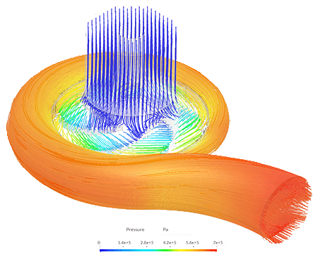
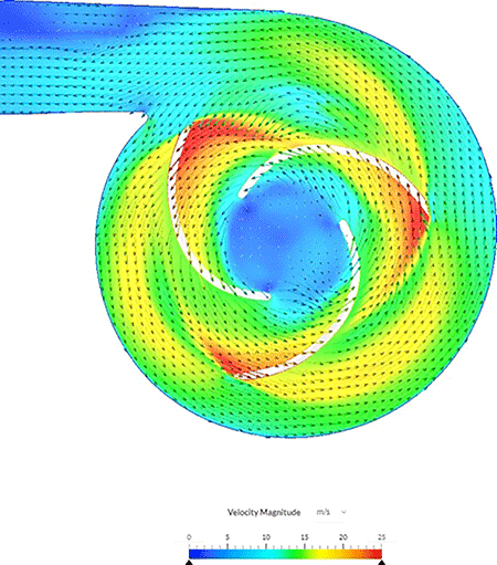
Simulating pumps and systems using computational fluid dynamics (CFD) and finite element analysis (FEA) is a valuable approach for designing and analyzing fluid, thermal and structural behavior. CFD and FEA involve mathematically simulating fluid and structure mechanics using software programs that replicate the behavior of fluids under realistic assumptions. It models heat transfer mechanisms, such as conduction, convection and radiation, as well as fundamental fluid properties like viscosity, density and turbulence. This allows CFD to generate valuable data on the velocity, temperature and pressure of moving fluids and predict effects such as cavitation, which occurs when insufficient pressure at the suction end of a pump causes the liquid to vaporize. Similarly, by using FEA, engineers can calculate loads, stresses and failure points of pumps and turbomachinery designs.
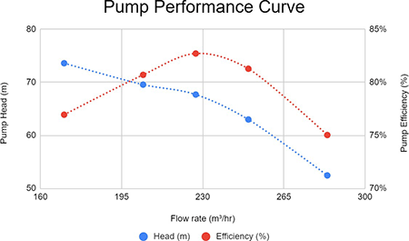
In the context of pump design, a 3D computer-aided design (CAD) model is used to represent the physical characteristics of the system and apply boundary conditions for the simulation setup. By manipulating the 3D model and boundary conditions, various pump configurations and environmental conditions can be simulated. For instance, different blade angles or fluid inlet temperatures can be tested to determine the optimal pump performance and generate entire pump/turbine performance curves, or be used to verify manufacturer performance.
Digital Transformation in Pump & Turbomachinery Design
Cloud-native simulation tools enable engineers to explore, test, validate and optimize product designs in a web browser. By incorporating simulation early in the design process, engineers can identify design strengths and weaknesses, saving time and costs associated with physical testing and prototype work.
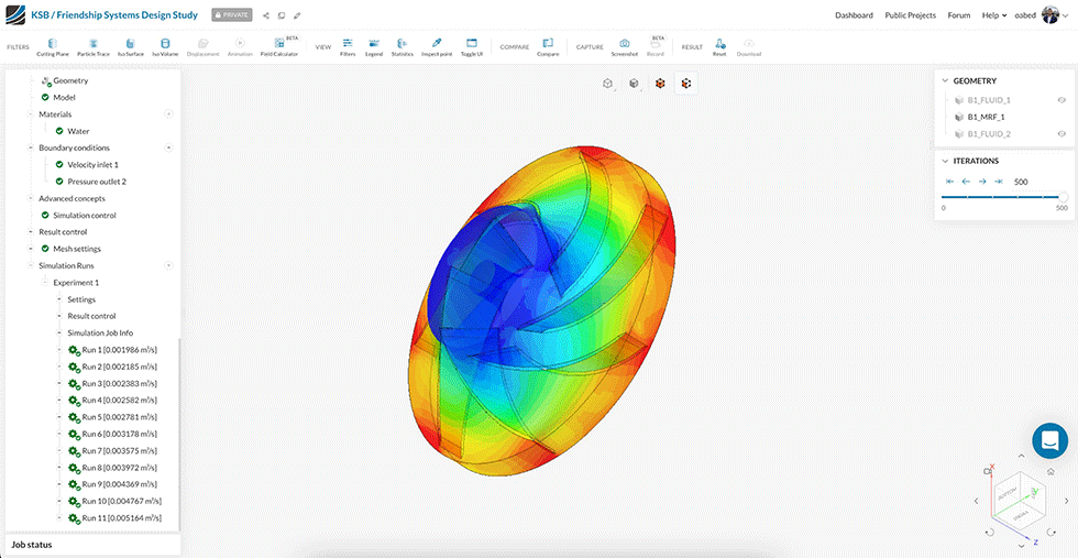
Cloud computing makes simulation more accessible and scalable for teams and organizations. Modern simulation tools need fast simulation times, parametrization capabilities and application program interfaces (API)-enabled design variations that make them suitable for complex geometries with efficient simulation setup and runtime. The turbomachinery solver referenced in this article has a binary tree mesh based on the physics of the analysis, meaning it is generated after the simulation setup to fully account for the physics and model properties. Because the mesh has a high quality, it requires fewer cells to achieve the same level of accuracy.
The key advantages of using this approach include fast simulation times and the ability to perform scenario analysis in parallel using input condition parametrization and API-enabled geometric design variation. Even for intricate geometries, users benefit from fast simulation setup and runtime.
Advances in Pump Engineering Simulation
In some industries, CFD simulations are particularly relevant for predicting multiphase flow behavior, where two or more liquids are present, like in oil industry applications. These simulations consider factors like oil density, temperature variations and viscosity. By running simulations at different temperatures, engineers can evaluate the impact of density and viscosity on pump efficiency and power requirements. This is especially useful in offshore applications where oil pipeline temperatures fluctuate seasonally. The insights gained from CFD simulations help assess the additional power load on the pump due to changes in oil density and temperature, for example.
Advanced multiphase solvers utilize a volume-of-fluid algorithm with a higher-order reconstruction scheme to model the interface between fluids accurately. This means they can model real properties from an extensive materials library with fast visualization of the flow field and phase fractions and, coupled with cloud-computing, offers an order of magnitude improvement in time and efficiency of design simulation. This is important because traditional flow simulations have been computationally intensive and time-consuming, limiting their use in early stages of product development. Cloud-based simulation, however, leverages scalable high-performance computing and offers flexible pricing models, providing accurate and cost-effective alternatives to desktop-based workflows with expensive hardware and licensing requirements.
Performance Design & Testing
A case study involving the hydraulic design of heating circulator pumps showcases the effectiveness of simulation in meeting energy efficiency requirements. Simulations using CFD were conducted to analyze 300 design variations of the impeller, considering multiple operating points. The results were stored in a surrogate model, which facilitated rapid impeller selection in the final stages of product development. By utilizing the cloud-based simulation platform, parallel simulations reduced the total cumulative runtime, resulting in time and cost savings.
Industrywide Collaboration
Collaborating with industry leading third-party tools is a win-win for turbomachinery engineers. An example of this integration is a coupled workflow between a leading simulation software and a turbine design tool. Integrations provide functionality for users interested in seamlessly creating CAD models of turbomachinery products such as turbines, pumps, compressors and fans, and running simulations to evaluate their blade profiles, pressure-flow characteristics and efficiency requirements in connected simulation tools. Engineers can use these coupled workflows to initiate a complete design process of a turbomachine starting from as little as an initial design point as the input. The turbine design tools include an export interface that lets its users export geometry directly into the simulation software and start simulating immediately. The workflow is enabled using API, which read the exported 3D Standard for the Exchange of Product Model Data (STEP) files and related model settings from various blade design tools and make these simulation-ready. Users can then follow the easy-to-use interface to run simulations, post-process the results and create insightful and compelling visualizations.
Modern cloud-native tools offer robust CAD handling capabilities, automated meshing and high solver accuracy. These tools enable engineers to analyze subsonic and supersonic flow behavior, turbulence effects, cavitation, multiphase flows and conduct static and dynamic analyses for structural integrity, vibration and thermal stresses.