


From the moment an end user is ready to put a motor into operation, their motor knowledge is being put to the test. Are the control systems ready? What about the foundation to specification, both structurally and dimensionally? Has the installation environment been accounted for? The answers to these questions and many more can all be found in motor technical data.
Motor technical data is broadly categorized into three types: electrical data, mechanical data and service data. These data are communicated to motor users through a range of forms including motor nameplates, data packets, technical drawings and service-related materials. Nameplates serve as the simplest summation of all motor technical data and are intended to be snapshots of the most critical motor data. Data packets expand mostly on electrical data but often include limited mechanical details and information if the motor was designed for a particular specification. Technical drawings provide mechanical details and might include items like outline drawings or shaft detail drawings. Service-related information comes in forms including operations and maintenance (O&M) manuals and critical spare parts lists. Understanding motor technical data is advantageous to end users by offering a complete picture of a motor that will lead to increases in reliability and keeping motors from operating in ways they were not intended to. This article provides a brief explanation of common technical data to support end users in optimizing the use of motors.
Nameplates
Nameplates are a snapshot of the most critical motor electrical, mechanical and service information. They are meant to be a (mostly) permanent physical record of critical information to positively identify machines to manufacturers for service or replacement and give service personnel quick reference data for diagnostics. Some of the most easily recognizable data are items like horsepower (hp), revolutions per minute (rpm), voltage, full load amperage (FLA), number of phases, hertz (or frequency), frame size, weight and enclosure. Beyond this, additional electrical data are included on nameplates that are less understood by end users. This includes design (or design letter—a National Electrical Manufacturers Association [NEMA] designated letter summarizing transient performance), code (or kilovolt-ampere [kVA] code letter—a NEMA designated letter relating locked rotor current [LRC] to total power), insulation class (for example F or H, which give limits on acceptable internal temperatures), ambient (the maximum environmental temperature the motor is designed to operate at), service factor (an acceptable overload), and duty (or “time rating,” which gives the maximum length of time a motor can operate within its temperature limits). Less understood mechanical data includes bearing designations (American Bearing Manufacturers Association [ABMA] codes or bearing manufacturer designations), lubrication information (acceptable greases or forced lubrication flow) and various accessory information.
Other information listed on nameplates not related to electrical or mechanical characteristics is largely meant for service references and identification to OEMs, as well as confirming compliance with required end user specifications. Motor manufacturer designations include fields such as model number, serial number, type or catalog number. Specification data includes special markings, standards names or insignia that detail what industry or end user specifications a motor was manufactured in accordance with. This could include designations such as NEMA MG-1, American Petroleum Institute 546 (API 546), Underwriters Laboratories 674 (UL 674), etc.
Data Packets
When procuring or servicing a motor, it is always a good idea to ask for expanded data packets from OEMs so accurate and complete comparisons can be made between different machines. Data packets can be simple, single-page summary sheets of electrical, mechanical and specification characteristics or multipage documents that provide various performance curves and summaries of factory tests. At a minimum, data packets will repeat the information given on a motor nameplate, but more typically they will expand on the motor performance and include transient operating characteristics. For example, instead of only providing the kVA code letter, which gives a range of expected LRC values, a single value will be provided so that proper relay and trip settings can be set. Similarly, instead of only providing a design letter—which gives a reference for minimum expected locked rotor (LRT), pull up (PUT), and breakdown torque (BDT) as well as maximum values of LRC and full load slip (the percentage away from synchronous rpm a motor should operate)—a data packet will provide specific values for these data points.
Tables expanding on expected efficiency, power factor, rpm and amperage at various load levels in percentage of rated hp are also common in data packets. This data can be helpful diagnostic information if motors regularly operate at load points other than nameplate hp. Other rated load data that might be presented here are expected noise levels at a specified distance (e.g., 3 feet from the motor) and in a specified scale (e.g., decibel A-Scale), full load torque (FLT), or details on required external airflow to maintain motor temperature rise.
Common mechanical information specified in data packets includes rotor conductor material for squirrel cage motors (e.g., copper versus aluminum), expected motor rotor weight and inertia, and detailed bearing information. Additionally, some specific information such as type of stator coils (e.g., formed [made prior to insertion into slots] or random wound [made while inserting into slots]) and how many stator and rotor slots the motor has. This information is helpful for vibration diagnosis and repair quotations.
Technical Drawings
Technical drawings provide useful information beyond what a nameplate offers. Technical drawings illustrate the physical features and dimensions of motors so that proper installation can be carried out. The most basic mechanical information in this category includes outline drawings (often called general arrangement or GA drawings). Outline drawings provide full dimensional data on motors so that end users can know the dimensions and locations needed for foundation bolts for motor feet or flanges, coupling bores and axial locations for mounting to driven equipment, as well as locations of conduit entrances on motor terminal boxes. Also common in outline drawings are detailed weight breakdowns on the motor and its commonly disassembled components, as well as labeling of points where it is safe to lift either the complete motor or its removable assemblies. Regarding lubrication and bearings, outline drawings delineate the points where oil or grease can be both fed and discharged from the motor as well as details on oil feed requirements for motors using forced lubrication. Various clearances needed (either for proper ventilation or removal of items like the motor rotor or air inlet filters) are also provided on detailed outlines so that end users can make advanced arrangements for nearby equipment and overhead hoists.
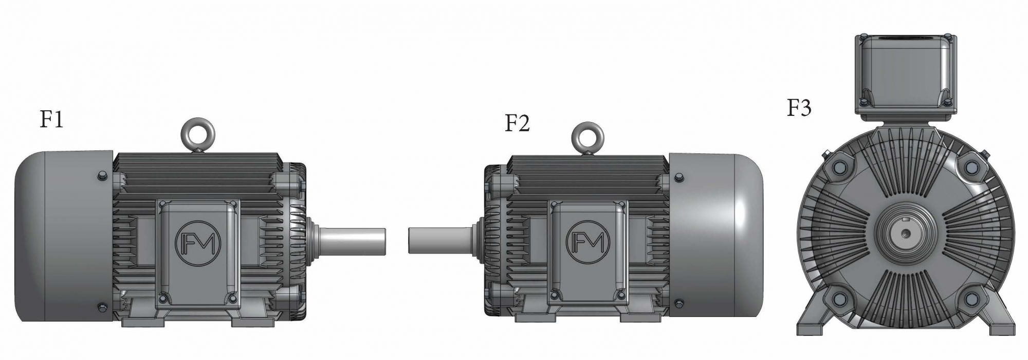
Another area that often causes confusion on outline drawings is naming conventions for both motor components (for example, junction box versus peckerhead or top hat versus air cabinet) and directional labels (for example, drive end versus fan end or pulley end). Rotation direction can often be misconstrued as what most motor manufacturers refer to as the “front” of a motor is actually the end opposite the shaft extension, and rotation is often specified in reference to “facing front end of motor.” There are also motor industry specific labels for where a main conduit box is on a motor that can be seen on outlines, including F1 (box on left side of motor facing shaft extension), F2 (box on right side of motor facing shaft extension) or F3 (box on top of motor).
If drawing packets are expanded beyond outlines, they often include junction box detail views, shaft torsional/shaft layout details (usually given to driven equipment manufacturers for detailed rotordynamic analysis), or sometimes top-level motor assembly drawings. Outside of dimensional data, one area of transient operating data sometimes found on large motor drawings is foundation loading information. If given, this data will usually be shown as loads on the motor feet under various conditions including at standstill (motor not operating), full load, maximum operating torque—known as breakdown torque or BDT—or fault torques including a stator phase-to-phase short circuit condition.
Service-Related Information
The final technical data category includes information typically only used when a motor is being commissioned, analyzed or serviced. The most common set of information in this category is O&M manuals. These are typically lengthy documents that are written to be utilized across a wide range of motor types and models. For example, a manufacturer might use the same O&M manual for all their horizontal, totally enclosed fan-cooled (TEFC), antifriction bearing induction motor models but have separate manuals for vertical motors or synchronous motors. The information found in these manuals includes expected foundation bolt torques, relubrication schedules, warranty contact information, filter cleaning procedures, common fault/troubleshooting methods and the like. The expectation with these manuals is that they can serve as a first reference point when there are questions about how a motor should be installed or serviced, prior to getting the manufacturer involved.
Other service-related information includes items such as critical spare parts lists, bills of materials (BOMs) and component detail drawings, though this information is rarely provided. While these items can be helpful to end users, manufacturers have to bear the burden of making sure distributed data is current with manufactured parts and, therefore, do not typically provide these items unless explicitly requested. These data sets are usually only seen on orders from end users who are at risk for large production losses associated with downtime or lost motor reliability. Items like a spare parts list or BOM, when used with the motor’s serial and/or model number, can help an end user or service center and motor manufacturer quickly identify part numbers for failed components so that expedient part ordering and replacement can ensue.
Putting It to Use
While this article provides a general overview of the common technical data seen with industrial electric motors, any one of these categories could be explored at length to provide even deeper motor understanding. If motor users take the time to understand the data types discussed here and apply data as the manufacturers intend them to, more reliable operation and more effective service of these machines can be achieved.