


Editor’s Note: Lev Nelik received many comments on this subject after Part 1 (Pumps & Systems, January 2012). Alberto Delgado, a former process engineer with Brown & Root, provided interesting feedback and detailed figures that resulted in several exchanges of ideas between the two. This information is presented as a follow up on this advanced and specialized subject of pump hydraulic design and is coauthored by Delgado.
Apparently, impeller velocity triangles do keep some folks awake at night. Part 2 contains information that is similar to what was discussed in Part 1, but it includes more detail regarding the vectors for each vane outlet at the same location for the three types of impellers. This detail will hopefully make the interpretation of the triangle more realistic.
We have shown only three positions on each type to provide the best possible illustration without sacrificing clarity. This also helps show, more clearly, the velocity vectors on Figures 1 and 2 from Part 1.
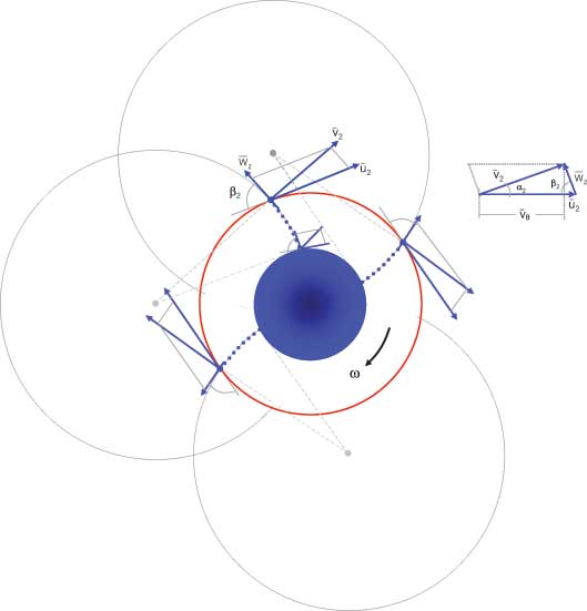
Figure 1. Backward-bladed centrifugal impeller (β < 90 degrees)
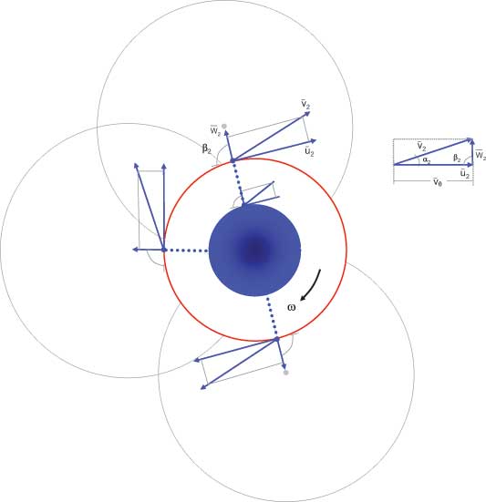
Figure 2. Radial-bladed centrifugal impeller (β < 90 degrees)
As shown in Figures 1 and 3, the locations for the backward and forward vane inlets are different, assuming that the same inlet vane angle is maintained. Note that the impeller curvature (inlet and outlet) is set by a circumference used to fix the relative inlet and outlet velocities. A tangent is drawn to the inlet and outlet from the center of the circumference. Inlet and outlet peripheral velocities are drawn using tangents from the center of the impeller.
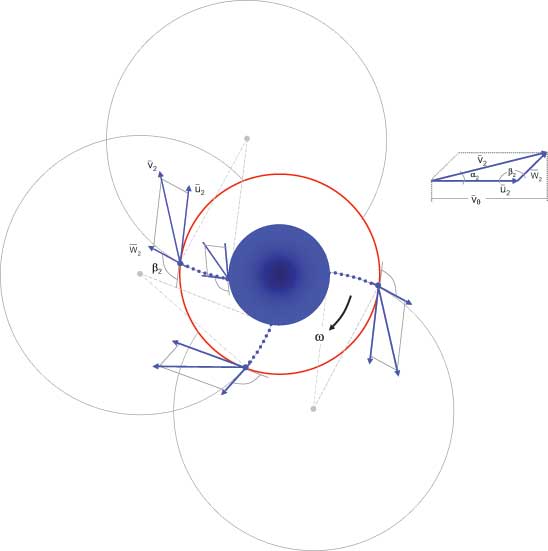
Figure 3. Forward-bladed centrifugal impeller (β < 90 degrees)
In the case of the radial impeller (see Figure 2), the vanes are straight to the center of the circumference. Any vane curvature is ignored for simplicity.
Note that for the turbopump (see Figure 4), the flow vectors for its turbine wheel, which has the flow direction reversed compared to the pump impeller, are shown as inflows rather than outflows like the other examples. In particular, note the match between the vectors at the inlet of the pump and the outlet of the turbine wheel.
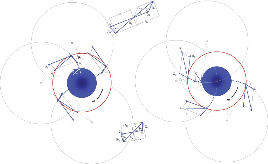
Figure 4. A pressure recovery hydraulic turbine, backward bladed (left) and a turbopump, forward bladed (right)
We also assumed, for simplicity, that the tangential velocity components at the pump impeller outlet can be considered equal to the turbine inlet and the turbine outlet equal to the pump inlet.
The following legend applies to Figures 1 through 4, which are used to illustrate the velocity triangles:
U = rotational, peripheral, tip velocity vector
v = absolute resultant velocity
W = relative velocity to blade tip
α = absolute vector angle
β = blade vane angle
ω = angular, rotating velocity