


Both centrifugal and positive displacement vacuum pumps are designed to remove molecules from a closed chamber at a fixed rate (volumetric capacity). When the vacuum pumps are working properly, the system pressure pump-down time can be tracked on a graph like in Image 1.
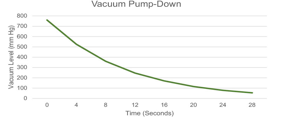
The pressure range is determined by the application/equipment and the time (in this case in seconds) is adjustable based on the physical size of the chamber. The largest vacuum chamber in the world at the National Aeronautics and Space Administration (NASA) in Cleveland would need to be graphed in hours (not seconds or minutes).
The graph in Image 1 is plotted by measuring the vacuum pressure at given time intervals after the vacuum chamber
is sealed (closed). Pressure is defined as force per unit area. The force air molecules can be unnoticeable considering they are always there. Less air pressure can be noticed in Denver due to its high elevation compared to New Orleans, which is at sea level.
Typically, a vacuum system consists of a vacuum pump, piping, a pressure gauge and a chamber with molecules in it (air pressure). As the vacuum pump captures and removes some of the molecules, the pressure begins to decrease—therefore, vacuum is being created.
The chamber pressure is the result of the molecules hitting the chamber or vessel walls. As the number of molecules inside the chamber decreases, both their force hitting the walls and the frequency of them hitting the walls decreases. This decrease is measured via a pressure gauge.
Vacuum systems leak in the opposite direction of compressed air systems or liquid systems. Finding leaks on compressed air systems or liquid systems generally involves listening to the whistling of escaping air or finding puddles and looking up into the piping. Vacuum system leaks are into the chamber or piping, so they can be more challenging to find and repair.
Often, vacuum system leaks are initially thought to be vacuum pump problems. The decision to change the vacuum pump should be based on measurable data and not just a gut feeling.
It is possible the air leak into the chamber may be equal to or more than the volumetric capacity of the vacuum pump. In this case, the air in-leak may be faster than the vacuum pump’s volumetric capacity, and this prevents the decrease in the vacuum pressure inside the chamber. The vacuum pump could be working correctly, yet the vacuum pressure is not decreasing.
The vacuum pump-down graph in Image 2 shows three separate chamber pump-downs. The green line shows a leak-free system, the blue line shows effects of a small leak and the red line shows the effect of a larger air in-leak. In all three pump-down graphs, the vacuum pump is working properly, even though the results (the pressure readings) are different.
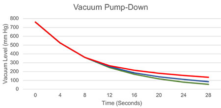
There is an additional issue involving air in-leakage. The volume of air passing through a leak changes with the differential pressure across the leak. Generally, the outside air pressure is not changing, but as the air pressure inside the vacuum chamber is decreasing, the overall differential pressure is increasing, which increases the volume of air passing through the leak. To put it another way, as the pressure inside the vacuum chamber decreases, the volume of air passing through the leak increases, which decreases the ability for the fixed volume vacuum pump to remove the air in-leakages volume.
Even though the vacuum is working properly, the air in-leak shown by the red line in the Image 2 may prevent the end user from conducting their process effectively. Changing the vacuum pump will not fix this problem.
Identification of an air in-leakage problem versus a vacuum pump problem should be one of the first steps in
troubleshooting a poor base pressure problem in a vacuum system. Identification of the root problem can prevent wasting time fixing a problem that does not exist. Producing a time versus pressure graph is usually a critical tool that aids in the effort to diagnose the causes.
In recent years, there have been advances in thermal imaging and sonic listening devices that can making finding air in-leakages possible or easier. It has been found that the gas flow through a leak can measurably lower the temperature in and around the leak. Newly developed thermal imaging systems (that a human eye cannot see) make this temperature difference visible, thus making it easier to pinpoint the leak location. Sonic listening devices can also assist this effort.
Finding the leak is the first step in correcting an air in-leakage problem. This may involve tightening a gasket, improving the gasket material or fixing a porous weld. A new pressure versus time graph can prove the corrective actions taken were successful.