


Partial discharge (PD) testing on high-voltage electric motors has been in use for a long time. However, PD testing on low- and medium-voltage motors is quickly growing in use among industrial maintenance and reliability professionals who work with pumps and systems.
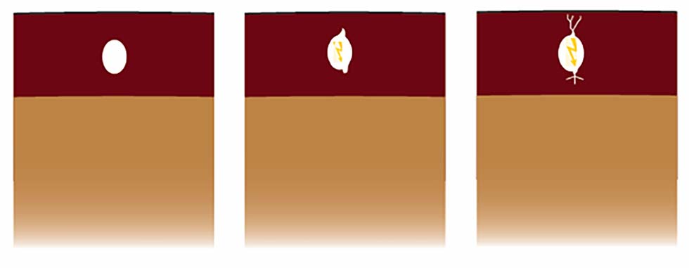
the void. (Images courtesy of Electrom Instruments)
Many factors contribute to PD activity in industrial pump motors. If undetected or increasing, PD can cause eventual dielectric failure in the insulation system and shorten the equipment’s useful service life. PD is one of the major contributors to the degradation and failure of insulation systems in all rotating equipment.
This article will describe the basics of PD, how it is measured and what maintenance and reliability professionals can do to protect their pump motors from failure and unplanned downtime.
What Is Partial Discharge?
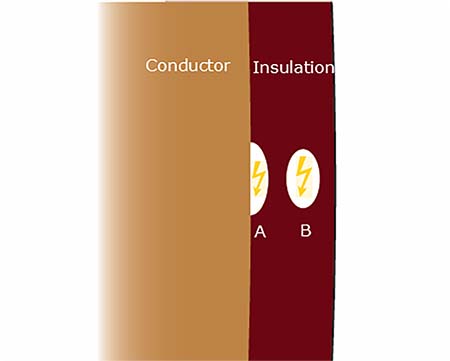
According to the International Electrotechnical Commission (IEC) 61934 standard, partial discharges are “localized electrical discharges that only partially bridge the insulation between conductors.” PD is a consequence of local electrical stress concentrations either inside the insulation (internal PD) or on the insulation’s surface (surface PD).
Surface PD occurs when the local electric field stress is enough to ionize the air near the winding surface. Surface PD is generally easy to detect visually as it releases ultraviolet (UV) light, and a tiny spark is sometimes seen. White or black powder is also sometimes present on the surface of the insulation because of PD.
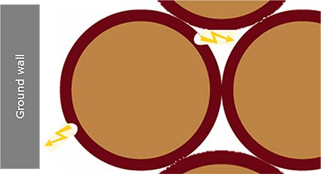
Internal PD can occur in any insulating medium used in rotating machines that are subjected to high electrical fields. It is initiated in microscopic voids, cracks or inclusions within a solid dielectric, at interfaces within solid or liquid dielectrics or delamination at the boundary of different insulation materials.
PD can cause progressive and irreversible damage to insulation systems. It creates localized spikes in temperature that produces caustic chemicals such as nitrogen oxides, ozone and nitric acid. It also generates a small plasma burst and emits UV light. All these stresses damage the insulation. With more damage, PD activity increases, which then causes more damage. The process can continue in a positive feedback loop until the insulation is unable to withstand normal electrical stress, which leads to complete dielectric breakdown and equipment failure.
PD testing on high-voltage motors and generators has been used in the industry for a long time, however, PD testing is quickly growing in use as more variable frequency drives (VFDs) or VFD power systems are used to drive low- and medium-voltage motors. If applied incorrectly, VFDs can be severely damaging for several reasons.
A bad VFD system causes large voltage spikes or voltage “overshoot” on the motor terminals. If the voltage spikes are high enough, they cause PD in the motor windings. Furthermore, these voltage spikes come at a high rate, from 500 to 20,000 times per second. Insulation breakdown is rapidly accelerated with large voltage spikes at high frequencies. Therefore, more quality control and reliability testing programs are using PD testing.
How Is PD Measured?
Various methods are used to detect PD, including the detection of sound, light and radio frequency (RF) signals. The alternating current (AC) hipot test with capacitive coupling is commonly used. This article focuses on PD detection using a surge test. This newer method is becoming popular and is a cost-effective solution when surge and other tests also need to be conducted.
To find PD activity with a surge test, voltage is pulsed into the windings of the motor or generator by a surge tester. Voltage is increased in small steps until PD is detected. Properties such as magnitude and polarity are measured by the instrument.
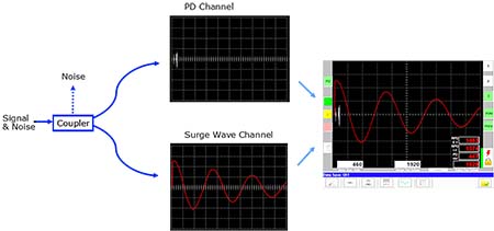
The PD pulses, or spikes, ride on top of the surge test wave. These high-frequency voltage spikes are filtered through an internal coupler and passed to an oscilloscope PD channel. The surge waveform and the PD voltage spikes are then combined on the same display screen with the PD signals along the center line. The PD signals are small compared to the surge voltage and are measured at different voltage ranges.
PD magnitude is measured in millivolts (mV) or picocoulomb (pC). Both measurements are a relative measure of PD activity due to several factors. First, PD pulses are attenuated and distorted as they propagate through the stator winding and travel from the source to the measurement point. Other factors that affect PD are humidity, contamination on the windings, and background electromagnetic noise levels. Therefore, the PD measurements obtained using different methods or equipment cannot be directly compared. The IEC standard recommends that PD measurements are trended since some amount of PD is acceptable in medium- and high-voltage motors. For low-voltage motors, there should be no PD at normal test voltages, so trending is not critical unless tests are done at higher-than-normal voltages.
How Do I Protect My Pump Motors?
Maintenance and reliability professionals can do several things to protect their pump motors. First, regular offline testing should be conducted. This provides valuable data that can be incorporated into a maintenance and reliability program. PD measurements should be taken during the commissioning of new equipment to establish a baseline. Once in operation, PD measurements should be incorporated into a regular maintenance cycle during planned downtime.
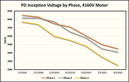
Any amount of PD detected in low-voltage motors is considered bad. All medium- to high-voltage motors have PD at some test voltage, but they are usually designed and built to withstand some level of PD activity. If testing shows PD activity increasing over time in medium- and high-voltage motors, the insulation system may be breaking down or weakening. Increasing PD activity is directly related to the voltage at which PD starts, known as repetitive partial discharge inception voltage (RPDIV). The lower the RPDIV is, the higher the PD activity is and the weaker the insulation systems are. Using data from the tests, strategic maintenance decisions must be made to ensure maximum asset availability. Second, using the right instrument makes all the difference. Look for an instrument with the following capabilities:
Trend capture
Because PD activity often presents itself well in advance of dielectric failure for medium- and high-voltage motors, maintenance professionals should track it over time and make data-driven strategic decisions regarding reconditioning or replacement of the equipment. PD trend detection is essential to ensure reliable, long-term operation.
Multiple tests
Electric motors are vulnerable to many stresses in addition to PD. Today’s advanced testers use multiple tests for complete motor diagnostics. For example, if monitoring shows a falling trend in RPDIV levels with the latest result falling below an acceptable limit, a problem exists and action should be taken. However, contamination on the windings can also contribute to lower PD inception voltages so results from other tests, such as insulation resistance, must be taken into consideration. Insulation resistance, direct current (DC) hipot and surge are additional tests that are typically used alongside PD.
Ease-of-use
In real-world field-testing applications, several different tests can be conducted in an automatic sequence to get the job done in a timely manner with the same procedure every time regardless of test operator. This produces consistent results and reduces the possibility of user error and differences in manual tests performed by multiple operators.
PD is a consequence of local electrical stress concentrations, which can cause progressive and irreversible damage to motor insulation systems. PD can be detected and measured using a surge tester. Asset managers and motor reliability professionals should monitor PD levels and conduct other common motors tests as part of a regular maintenance schedule. Increasing PD activity, or the presence of PD in low-voltage motors, is the earliest indicator of insulation breakdown. Hence, adding PD measurements to the arsenal of available motor tests gives asset managers valuable information to help keep their pumps running.